Everything you wanted to know about phase dimming and were too scared to ask.
1 Introduction
In this post we describe how phase dimming works, and show some practical effects of phase dimming with modern LED lamps and LED drivers.
1.1 Background and History
Phase Dimming is sometimes also called Phase Cut Dimming, or Phase Control Dimming.
Phase Dimming is one of the simplest ways of dimming incandescent electrical lamps. With phase dimming of an incandescent tamp, the amount of power delivered to a hot glowing wire is easily varied to create a useful form of brightness control.
After the invention of LED lighting, Phase Dimming is still commonly used. Instead of a glowing hot wire, the LED lamp driver needs to interpret the phase dimming waveform and voltage to create a dimmed signal for the LEDs. This is normally in the form of reduced LED current.
Because LEDs make light in a completely different way to incandescent lamps, there are significant challenges associated with dimming LED lamps, and with the resulting behaviour of the lamp and phase dimmer.
2 Basic Principles of Phase Dimming
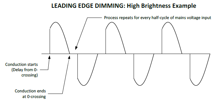
2.1 Leading Edge Dimming
(Leading Edge phase dimming is also called Rising Edge or Forward Phase Cut)
Leading Edge phase dimming is typically performed using a Thyristor (Silicon Controlled Rectifier or Triac). It works by looking for the mains voltage 0-crossing, delaying a little, and then switching on for the rest of the mains half-cycle.
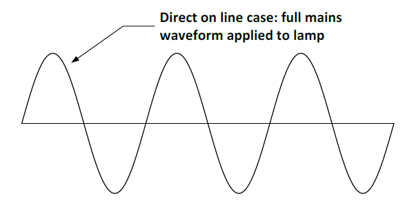
The following diagrams show:
- The voltage applied to a lamp when there is no phase dimmer.
- The voltage applied with Leading Edge dimming and a high brightness setting. Most of the mains voltage is applied to the load.
- The voltage applied with Leading Edge dimming and a low brightness setting. Only a small amount of the mains voltage is applied to the load.

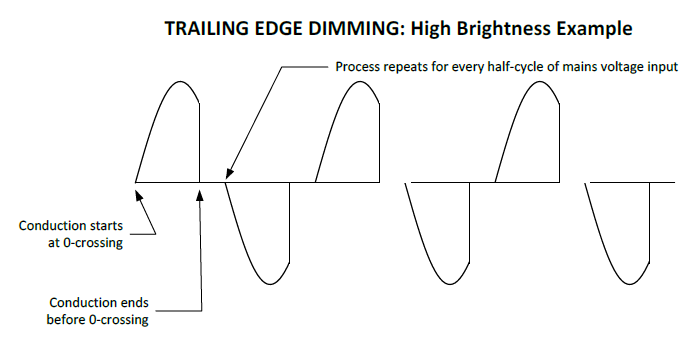
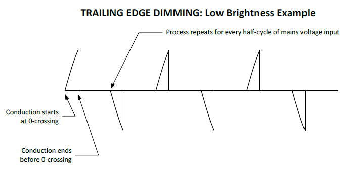
2.2 Trailing Edge Dimming
(Trailing Edge phase dimming is also called Falling Edge or Reverse Phase Cut)
Trailing Edge phase dimming is typically performed using a MOSFET. It works by passing the mains voltage to the load, starting at the 0-crossing of each half cycle, and then switching the mains conduction off part way through the half cycle.
Usually, trailing edge dimming is more suitable for LED lighting loads. It is also more complex to make a trailing edge dimmer.
The following diagrams show:
- The voltage applied to a lamp when there is no phase dimmer.
- The voltage applied with Trailing Edge dimming and a high brightness setting. Most of the mains voltage is applied to the load.
- The voltage applied with Trailing Edge dimming and a low brightness setting. Only a small amount of the mains voltage is applied to the load.
2.3 Obvious differences between Leading and Trailed edge types
Leading Edge dimming has a delay after the zero crossing, and then a turn-on during the mains half-cycle.
Trailing Edge dimming begins at the zero crossing, and then has a turn-off during the mains half-cycle.
3 EFFECT ON LOADS WHEN USING PHASE DIMMING
3.1 Power Delivery
Both leading and trailing edge phase dimming deliver the mains voltage to the load in the form of pulses, and these have the shape of a sine wave that has part of the wave shape removed.
For an incandescent lamp, the hot wire has a thermal reaction time (“thermal inertia”), and the pulses are not visible. The effect is to deliver less average electrical power to the lamp.
For an LED lamp, the pulses of power also deliver less electrical power, but as LED lamps have a low power rating, the lamp and its driver need to:
- Use the power pulses that are supplied to run the lamp; and also
- Interpret the power pulses to work out the brightness level.
3.2 Lamp (Driver) Reaction
Incandescent Lamps
Incandescent lamps just use the average electrical power supplied to pass through a resistive wire, which glows. The glowing wire makes light and heat.
When there is less power supplied because some of the voltage is removed (turned off), the effect is to put less energy into the resistive wire, which means it glows less. When it glows less, it makes less light and less heat.
LED Lamps
A LED lamp, by comparison, can extract all the electrical power it needs from the short voltage pulses that a phase dimmer provides. The LED lamp therefore uses extra electrical circuits to measure the pulse width and the time between the pulses. From that information it works out a dimming level and adjusts the amount of electrical power to put into the LEDs.
Different LED lamp (or LED driver) manufacturers will have a different reaction to the phase dimming pulses.
This may show up as differences (from one lamp supplier to another) between some or all of these characteristics:
- Dead-band at the top of the dimming range;
- Dead-band at the bottom of the dimming range;
- Minimum available brightness.
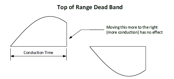
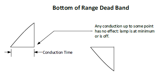
3.3 Dead Bands
A dead-band is a range of brightness adjustment where there is no reaction (no change in the amount of light produced).
This might be seen on a rotary dimmer, where rotating the dial causes no change in brightness. This might happen at the bottom of the dimming range (low end dead-band) or at the top of dimming range (top end dead-band).
Typical dead-band behaviour, shown with reference to trailing edge dimming:
3.4 Typical Operation for Phase Dimmers and Lamps: 50 Hz Power System
On a 50 Hz power system, the line frequency is 50 Hz, so the period of the mains sine wave is 20 ms. Each half-cycle has a duration of 10 ms.
Conduction Time
As shown in the above diagrams, the period of a mains half cycle when the phase dimmer is conducting is called “conduction angle” or “conduction time”. This is normally measured in milliseconds.
Phase Dimmers
On a 50 Hz system, the conduction time can vary from between these theoretical limits:
- Minimum 0 ms (no conduction at all); and
- Maximum 10 ms (conduction of the entire half cycle).
Typical phase dimmers have these limits:
- Minimum: anywhere from 2 to 4 ms; and
- Maximum: anywhere from 6 to 8 ms.
High quality phase dimmers, such as those designed by Ozuno have limits:
- Minimum: 1 ms;
- Maximum: 8 ms.
When comparing phase dimmers: a bigger range of conduction times provides the largest possible range of control inputs to a phase dimmable lamp.
Phase Dimmable LED Drivers
The performance of a Phase Dimmable LED driver is determined by the driver design. Most phase dimmable LED drivers can accept this range of conduction times:
- Minimum: anywhere from 1 to 4 ms; and
- Maximum: anywhere from 6 to 8 ms.
If a phase dimmer produces a conduction time under the minimum that the driver operates with, this can cause:
- A dead band at the low brightness (lower levels have no effect); or
- Flicker / flashing; or
- The lamp may be off.
If a phase dimmer produces a conduction time greater than the maximum that the driver operates with, this creates a dead band at the high brightness, where increasing the dimmer brightness setting has no effect.
3.5 Relationship between Phase Dimmer Conduction time and Brightness
Most DALI LED drivers will have a specified adjustable range, this may often be stated as “5% to 100%” or similar. Most LED drivers do not clarify if the range is electrical power consumption or brightness.
Phase dimmable LEDs, and phase dimmable LED drivers often do not state a dimming range, so the behaviour can involve a lot more guesswork.
Based on measurements made by Ozuno, phase dimmable LED lamps, and phase dimmable LED drivers can generally be grouped as:
| Quality | Light Output Range | Conduction Time Range |
|---|---|---|
| High | 1% (or less) to 100% | 2 ms to 8 ms |
| Medium | 5% to 100% | 3 ms to 7 ms |
| Low | 10% to 100% | 4 ms to 6 ms |
When considering phase dimmable drivers:
- A comparison using the same driver and different lamps will cause different results;
(The LED lamp and driver have an interaction with each other.)
- Different phase dimmers are likely to cause different results.
(Different phase dimmer have different conduction time ranges, so may have different operating ranges on a driver or cause different dead bands.)
- When using several phase dimmable LED drivers on a single phase dimmer, we hope they all have the same response, but sometimes this will not be the case.
(Because phase drivers can react differently to the same conduction time.)
3.6 DALI Phase Dimmers and Phase dimmable LED lamps
When considering DALI phase dimmers and DALI drivers, the DALI standards require that complete system of phase dimmer + driver + LED lamp must comply with the DALI dimming curve which has a brightness range 0.1% to 100%.
Meeting this full range is difficult or impossible for many phase dimmer / driver / lamp combinations. Compliance with the requirements is achieved by means of:
- Using the same lamp and lamp driver on all tests;
- Setting a DALI minimum level so that the phase dimmer can produce a conduction time that is compatible with the chosen phase dimming driver and lamp, in order to demonstrate a dimming range and a curve that is compliant (or close to) that required by DALI.
The effect of this that many DALI phase dimmers may only work over a small span of the DALI dimming numbers – for example:
| DALI Level | Required Light Level (as lux % of maximum) |
|---|---|
| 86 | 1 |
| 111 | 2 |
| 145 | 5 |
| 170 | 10 |
| 196 | 20 |
| 229 | 50 |
| 254 | 100 |
This table shows that a DALI Phase Dimmer that can only dim to 10% light output would have a DALI level of 170, so there would be a very significant bottom end dead band: setting a DALI level below that limit would have no effect on the phase dimmable lamp.
Ozuno RAPIX DALI Phase Dimmers (when used with suitable lamp and drivers) can do phase dimming over the full DALI span of 0 to 254, corresponding to 0.1% to 100% light output.
Compensation for the effect of reduced DALI dimming range
Unlike some lighting control system that re-scale the dimming range when a minimum level is set, the DALI system applies a minimum level by setting a limit, and adjustment below this limit has no effect. This creates a bottom end dead band, and for some DALI phase dimmers and LED lamps this could be significant.
DALI Selection of Linear Curve Type
Some DALI phase dimmers allow selection of a “linear” curve instead of the DALI logarithmic curve.
In general terms, the linear “curve” produces a different problem: the control range is “bunched” at the bottom end. This is because the human eye response is logarithmic, so for example, producing a measured reducing of light (lux level) to 10% of an original value is seen by a human user as a brightness reduction of about 50%.
The only time using the “linear” curve type is beneficial is for a subset of phase dimmable LED lamps that already include a logarithmic response. The only way to tell this may be trial and error.
Although the selection of “linear” seems a convenient solution, the result is usually a poor user experience.
4 Suggested methods for showing levels in a DALI Phase Dimmer System
Try and avoid showing levels as numbers or percentage.
Reason: When showing levels as a percentage, this gives a misleading impression of accuracy and precision – for example “1%”, if measured with a light meter, needs to be around 1% of the maximum level. Similarly, 10% needs to be measured as 10% of the maximum.
The large variation between LED lamps, drivers, and their behaviour in a phase dimming system means that the precision shown by a percentage level can never be guaranteed.
In addition, the dead bands at the top and bottom of the phase dimming range may be caused by the phase driver, or the lamp, or both in combination. The dead bands will vary from one lamp to another, and again, using percentage levels when there is a dead band causes a poor user experience.
Suggestions for a better user experience: