Search
Close this search box.

DALI-2 Technical Guide

Get me quickly to:

What is DALI?

DALI is an acronym for Digital Addressable Lighting Interface. This defines a method to control and monitor lighting products.

The DALI standard is created and maintained by the International Electro-Technical Commission (IEC) and published as standard IEC 62386.

Sub-parts to that standard cover the communications method, data formats, operations of control gear (lamp drivers, relays and so on). Later releases of the standard added control devices such as switches and sensors.

IEC does not test or certify products; they only create, publish and maintain the standards.

The DALI Alliance is an industry group that owns the trademarks DALI and DALI-2, and associated logos.

DALI Alliance allows members to use those names and logos for equipment that has been tested and found in conformance with the standards. Depending on the equipment and standard, the conformance may be as a DALI registered product, or a DALI-2 certified product.

What is DALI-2?

DALI-2 is the trademark of DALI Alliance that members may use to show a product is tested to and conforms to the standards:

For Control Gear (lamp drivers, relays, dimmers):

  • IEC 62386‑101 Edition 2 or later
  • IEC 62386‑102 Edition 2 or later
  • IEC 62386-2xx Edition 1 or later, depending on device type.

For Control Devices (switches, sensors, and so on):

  • IEC 62386‑101 Edition 2 or later
  • IEC 62386‑103 Edition 1 or later
  • IEC 62386-3xx Edition 1 or later, according to input type

DALI Alliance will only certify DALI-2 devices showing that such devices have passed a rigorous test process devised by and controlled by DALI Alliance. Such devices may use the DALI-2 word in their description and may use the DALI-2 logo.

How does DALI-2 differ from DALI?

Edition 2 and later versions of the DALI standards (marketing name: DALI-2) are a significant re-write of the earlier standards.

The changes in the Edition 2 (DALI-2) standards are designed to increase interoperability, especially in situations in which an existing DALI product is to be replaced by a new DALI-2 product, or where DALI-2 Input Devices are to control DALI or DALI-2 Control Gear.

The update:

  • Eliminates ambiguities in previous versions;
  • has better definitions for electrical and communication properties (part 101 and 102) that help to ensure better interoperability between control gear from different manufacturers; and
  • adds definition for and support for control devices (switches, sensors, etc, also called Input Devices) in new standard IEC 62386-103.

Control devices are further specified by instance types for push buttons (part 301), analogue inputs (part 302), occupancy sensors (part 303) and light level sensors (part 304).

The most important changes in these standards are:

IEC 62386-101 (General Requirements – System Components):

  • Better specification for the properties of DALI bus power supplies;
  • Definition for behaviour of bus-powered devices;
  • Definition of devices with multiple logical units (multiple channels or device types in a single physical enclosure);
  • Better definition for device labelling;
  • Addition of frame format and timing for supporting control devices, including both single and multi-master types; and
  • Significant improvements in test sequences.

IEC 62386-102 (General Requirements – Control Gear):

  • A major re-write with significant clarification and improved definition of device behaviour;
  • Addition of new capability for extended fade times;
  • Definition of manufacturer specific modes; and
  • Significant improvements in test sequences.

IEC 62386-103 (General Requirements – Control Devices):

  • Newly added, and defines single and multi-master systems;
  • Definition of and specification of message formats and general operation for control devices; and
  • Definition of and specification of general messages related to Application Controllers.

Terms used

The DALI-2 releases of the standards use terms to have very specific meanings, which helps to remove ambiguity between manufacturers. A limited set of examples:

Application Controller:A device that performs a useful function, such as by operating on events from Input Devices, and telling Control Gear what to do.
Control Gear:A device that controls a lamp or electrical load. Typically a lamp driver, relay or dimmer.
Control Device:A device that feeds an input signal to a lighting control system. Typically a person will interact with control devices like switches and sensors.
Input Device:Another name for Control Device, and which is often easier to understand.
Occupancy Sensor:A generic term to cover sensors that detect a space is occupied by people. Occupancy Sensor is further broken down to Movement Sensor and Presence Sensor.

Short Addresses for Control Gear and Input Devices

Control Gear and Input Devices operate on the same DALI physical line but communicate in separate universes. Application Controllers join those universes together.

There are therefore two separate and distinct universes of DALI Short Addresses:

64 short addresses for Control Gear

and

64 short addresses for Input Devices (Control Devices).

It is therefore possible to have, for example, a lamp driver at Short Address 1, and a push button switch at Short Address 1. Those two addresses are completely separate to each other.

Commissioning software can show this in different ways – an example is shown alongside.

Compatibility of DALI and DALI-2

For Control Gear (lamp drivers, relays, dimmers, and so on), the same commands are used in DALI and DALI-2. This means DALI-2 devices can be easily used in previous DALI systems.

DALI-2 adds a small number of new commands and capabilities. This means that in some cases, older DALI products may impose a reduction of possible features in a DALI-2 system – as an example, the new extended fade times of DALI-2 can’t be used with an older DALI compatible product[1].

DALI Alliance has more information about compatibility here: https://www.dali-alliance.org/dali2/comparison.html

[1] Application Controllers may use work-arounds to allow this kind of function in any case.

Compatibility and Compliance Testing

Before the DALI Alliance was created, product testing by manufacturers was expected but not enforced.

Many products were created and marketed as “DALI” without any testing, or with notable incompatibilities or functional failures. This led to significant market frustration, with vendors blaming each other when products did not work as expected, or when products from different manufacturers in the same space showed different operation.

The formation of DALI Alliance has created a new control over the use of the DALI and DALI-2 names and their associated logos.

Every device using the DALI-2 word or DALI-2 logo should have been tested for conformance using standardised test equipment controlled by DAL Alliance. The Alliance also check results before certification is granted.

How to find if a product really is DALI registered or DALI-2 certified

Older DALI products that passed testing are known as DALI registered[2].

DALI-2 products that passed testing and certification of the test results by DALI Alliance are known as DALI-2 certified.

Both product types show an indication of product compliance, testing, compatibility and diligence by the manufacturer.

Where possible, DALI-2 certified products should be preferred because of compliance to an improved standard, with a demonstrated better level of testing.

Registered and certified products are listed by DALI Alliance in their product database, which is accessed at their web site: https://www.dali-alliance.org/products

A product claiming DALI or DALI-2 compliance or compatibility that does not appear in the DALI Alliance product database should be treated with caution – it is probably not tested or certified, it may not work well, and the manufacturer is likely to be in breach of the DALI Alliance trademarks.

[2] It is no longer possible to register a new DALI product.

What are DALI Control Gear Device Types?

DALI Control Gear is categorised according to what type of function it performs. These are called Device Types.

The following Device Types are defined by IEC standards:

Device TypeStandardDescription
0IEC 62386-201Fluorescent Lamps
1IEC 62386-202Self-contained emergency lighting
2IEC 62386-203Discharge lamps
3IEC 62386-204Low Voltage Halogen Lamps
4IEC 62386-205Supply Voltage Controller (typically but not limited to DALI to phase dim conversion)
5IEC 62386-206DC conversion (for example DALI to 0-10)
6IEC 62386-207LED lamps and modules
7IEC 62386-208Switching function (relays)
8IEC 62386-209Colour Control (typically RGW and tuneable white)

A number of additional Device Types are also defined. These specify additional features or capabilities, for example for energy reporting, diagnostics, and similar.

Important Devices Types for these capabilities are:

Device TypeStandardDescription
51IEC 62386-252Energy Reporting
52IEC 62386-253Diagnostics and Maintenance

A “hybrid device” has multiple device types, for example a LED driver with energy reporting would have Device Types 6 and 51.

What are DALI-2 Instance Types?

DALI-2 Input Devices define a method where a single physical device may contain several things that supply inputs – for example, a sensor that determines Occupancy and also measures light level. Each physical input is called an Instance, and each instance has an Instance Type. Instance types define what kind of input is processed. A sensor that contains both Occupancy detection and light level measurement might contain two instances, the first instance being Occupancy Sensor, and the second being Light Level Sensor. The following Instance Types are defined by IEC standards.
Instance Type Standard Description
1 IEC 62386-301 Push Buttons
2 IEC 62386-302 Absolute Input Devices
3 IEC 62386-303 Occupancy Sensor
4 IEC 62386-304 Light Sensor
5 IEC 62386-305 Colour Sensor
6 IEC 62386-306 General Purpose Sensor
Instance Types 1 – 4 are commonly used and available. Instance types 5 and 6 are less commonly used. A small number of other “feature” standards are also used, for example, Feedback and Manual configuration. These feature standards presently have no test methods and are not part of DALI-2 certification.

Typical DALI Installation Architectures

DALI standards define a variety of ways that Input Devices can cause a useful function by adjusting the lighting output of Control Gear.

DALI-2 includes the concept of an Application Controller.

The simplest definition of an Application Controller is:

“A box of tricks that makes useful stuff happen.”

Typically an Application Controller takes information from other systems, or from sensors and switches, works out what the action should be (in other words, performing the useful function) and then transmits commands to the Control Gear to set levels, run fades, and so on.

The Application Controller can be:

  • A separate physical device (for example, a RAPIX DALI-2 Zone Controller); or
  • It can be integrated in with another product (for example, a RAPIX DALI-2 sensor).

The methods for programming the “useful function” into Application Controllers is not defined by standards. Manufacturers use their own methods to do this.

Some examples of system structure are shown in the examples below. These examples are from IEC 62386-101, edition 2.

System structure:

There are separate logical components in a DALI-2 system

During normal operation, the typical flow of messages in a DALI-2 System is as shown:

Input Devices transmit messages that are received by an Application Controller.

The Application Controller works out what useful function should be performed, and then transmits commands to Control Gear that set the lighting accordingly.

The examples that follow are all possible and permitted combinations of DALI power supplies, Input Devices, Application Controllers and Control Gear.

The examples are also not a complete set – other combinations are possible provided that each of the parts exists in some form.

System Example – Single Application Controller
In this example, the Application Controller has an integral bus power supply. It only sends commands to Control Gear. This kind of system is commonly used where the Application Controller is a gateway from another system to DALI, and so the Application Controller functions as a protocol converter.
System Example – Multi-master System – Single Application Controller

In this example, all components are separate. The single Application Controller accepts EVENT messages from Input Devices, and after working out what function to perform, sends commands to Control Gear.

The DALI system needs to be muti-master: multiple devices transmit messages without interfering with each other. The method for this is defined in the standards.

System Example – Multi-master System – Multiple Application Controllers

In this example, all components are separate. Multiple Application Controllers send commands to Control Gear.

The DALI system needs to be multi-master: multiple devices transmit messages without interfering with each other. The method for this is defined in the standards.

To maintain system integrity, the multiple Application Controllers also need to have a means of working with each other. These methods are not defined by standards.

System Example – Multi-master System – Multiple Application Controllers Integrated with Input Device

In this example, a separate Application Controller is present alongside another Application Controller that is integrated with an Input Device.

Multiple configurations are possible:

  • The integrated Application Controller may process events from the Input Device, and transmit commands to the Control Gear; or
  • The external Application Controller may process EVENT messages from the Input Device and transmit commands to the Control Gear; or
  • Some combination of both of these.

The DALI system needs to be muti-master: multiple devices transmit messages without interfering with each other. The method for this is defined in the standards.

To maintain system integrity, the multiple Application Controllers need to have a means of working with each other. These methods are not defined by standards.

System Example – Multi-master System –Application Controllers integrated with Input Device and Power Supply

In this example, an Application Controller is integrated with an Input Device and a power supply.

The integrated Application Controller processes events from the internal and external Input Devices, and transmits commands to the Control Gear.

DALI-2 in a RAPIX Lighting Control System

Historical Perspective – RAPIX before DALI-2 switches and sensors

Before RAPIX sensors and switches were DALI-2 certified, the method of operation for a RAPIX system was:

Historically, RAPIX systems included an Application Controller in every switch and sensor.

All RAPIX Application Controllers co-operate with each other to minimise DALI bus traffic and to achieve useful functions.

RAPIX Zone Controllers have been used for functions such as:

  • Joining DALI lines to make systems bigger than 64 lighting Control Gear;
  • Running schedules;
  • Coordinating scenes distributed over multiple DALI lines;
  • Running customer logic code;
  • Providing an API for external systems access, including custom protocols, MQTT, Modbus, and similar; and
  • Cooperating with the Application Controllers built into switches and sensors, to achieve operations over more than one DALI line.

In a RAPIX system, the Application Controller built into switches and sensors always transmits commands to the Control Gear on its local DALI line.

This method creates a robust system where any failure of a Zone Controller, or the infrastructure that links Zone Controllers (ethernet) does not cause a totally inoperative lighting control system. A RAPIX system has a graceful degradation in the event of failures of system components.

Present Day – RAPIX with DALI-2 switches and sensors

RAPIX DALI-2 was released in February 2024.

This major upgrade includes the following additional functions and capabilities.

RAPIX Switches and Sensors

All RAPIX switches and sensors are now DALI-2 certified. These instance types are supported across the range of RAPIX Input Devices:

  • Instance Type 1 (part 301) Push Buttons;
  • Instance Type 2 (part 302) Absolute Input;
  • Instance Type 3 (part 303) Occupancy Sensor;
  • Instance Type 4 (part 304) Light Level Sensor.

All RAPIX switches and sensors are 100% DALI-2 tested and certified and can be used in any DALI-2 lighting control system – either RAPIX, or a system from another manufacturer.

In addition, RAPIX switches and sensors retain their integral RAPIX Application Controller, allowing it to process its local input (sensor, buttons or rotary dial), retaining the co-operation of RAPIX Application Controllers for superior resilience.

This built-in Application Controller function is a normal behaviour permitted by DALI-2 standards, and is typically disabled when used in a DALI-2 system from another manufacturer.

This means that RAPIX sensors and switches can be used in two major ways, with minimal setup by the Systems Integrator:

  • In a RAPIX DALI-2 system, the internal Application Controller is used for superior system reliability; and
  • In a DALI-2 system from another manufacturer, the internal Application Controller is not programmed and should be disabled. Instead standard DALI-2 EVENT messages are transmitted to an external Application Controller.

RAPIX Zone Controller

The RAPIX Zone Controller continues to cooperate with RAPIX switches and sensors, but in addition is upgraded so that it can also accept EVENT messages from any DALI-2 switch or sensor that supports instance types 1, 2, 3 or 4 – that is, any push button switch, absolute input, occupancy sensor or light level sensor.

When a RAPIX Zone Controller receives these messages, it uses the same template-based programming system used by all other RAPIX Input Devices to create a useful action.

A RAPIX DALI-2 system has the structure shown:

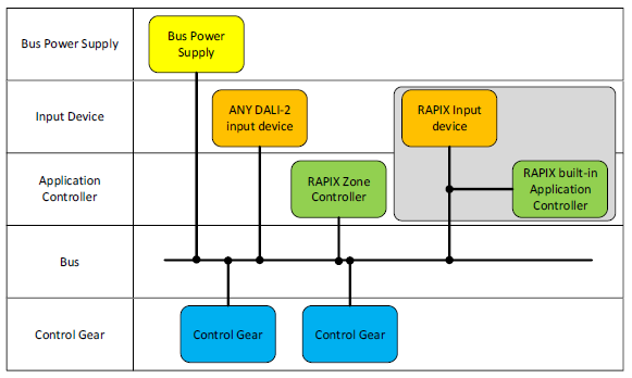
Consequently, RAPIX allows these possible combinations:

  • RAPIX Zone Controller with switches or sensors from another manufacturer (and no RAPIX switches or sensors);
OR
  • RAPIX Zone Controller with exclusively RAPIX switches and sensors;
OR
  • RAPIX Zone Controller with a mix of RAPIX switches and sensors and also switches and sensors from other manufacturers;
OR
  • Other manufacturer controller with RAPIX switches or sensors.

DALI-2 Instances

Purpose

DALI-2 Input Devices define a method where a single physical device may contain several physical inputs – for example, a sensor that determines Occupancy and also measures Light Level.

Each handler of a physical input is called an Instance, and each instance has an Instance Type. Instance types define what kind of input is processed.

Examples:

  • A wall switch unit that has 4 buttons would contain 4 instances, each of type “push button”;
  • A RAPIX sensor that has movement sensing capability, light level measurement and a push-button switch input would contain 3 instances: one of type Occupancy Sensor, one of type Light Level Measurement, and one of type Push Button.

The instance not only processes the input signal, it also creates status information and produces an output – typically in the form of a message called an EVENT.

Functionality

Typically, DALI-2 Input Devices do not send commands directly to Control Gear.

Instead a higher level control unit (the Application Controller) processes the status and events of all instances in the lighting system and then sends any required DALI commands to Control Gear.

The status information in instances allows an Application Controller to interrogate the product and determine the state (for example, occupied, or the light level measurement).

However, interrogation can be very slow. . Usually, instances in Input Devices are configured to send EVENT messages because these convey information quickly: such as button pushed or released, or occupancy determined.

DALI-2 commands for Input Devices include the ability to enable or disable different event messages and set their transmission priority and transmission frequency.

Instance Groups

To aid in system design, management and performance, instances may be assigned to instance groups. Using Instance Groups allows a number of products to cause the same outcome by an Application Controller. Examples:

Push Buttons

If (as an example) 3 push buttons switches are to have the exact same control effects on the same space in a building, then they might be assigned to Instance Group 1, and be set to transmit event messages using the Instance Group event scheme.

This means that each time any of those buttons are pushed, an event message will be transmitted indicating “Instance Group 1 created this message”. It is not possible to tell which of the switches transmitted the message, because the event messages look the same and have the same instance group.

The Application Controller is programmed to respond to event messages on Instance Group 1, performing switching and dimming operations on loads connected to DALI Control Gear located in the relevant space in the building.

Occupancy Sensors

Several occupancy sensors may control a space, typically by the function that if any of them determine occupancy then the space should have lighting switched on.

They might be programmed to use (as an example) Instance Group 2 and transmit events using the Instance Group event scheme.

An Application Controller can then determine that if “Occupied” events arrive (which could be from any of those sensors) the space is occupied and lighting should be switched on.

Similarly, if “Occupied” events no longer arrive, then the Application Controller can run a timeout period before switching the lighting off.

Event Scheme

An Event Scheme determines a method by which Input Devices announce their events. An Application Controller can be programmed to understand the events, according to the Event Scheme.

The following Event Schemes are possible, as defined by IEC standards.

Event Scheme No.DefinitionComment
0InstanceEvents include the instance type and instance number
1DeviceEvents include the device short address and instance type
2Device/InstanceEvents include the device short address and instance number
3Device GroupEvents include the device group and instance number
4Instance GroupEvents include the instance group and instance type

The event scheme that an Application Controller requires is defined in it’s programming documentation.

Event Filter

Each Instance Type has a list of possible events that it can generate. The events may or may not be useful, according to the needs of the Systems Integrator and the Application Controller being used.

An Event Filter allows events to be enabled or disabled.

If all events from all Input Devices were enabled, then excessive traffic on the DALI line may occur. By disabling events that are not needed, the number of messages transmitted can be reduced.

As an example, the events possible from a push button switch are:

Event NameDescription
Button releasedButton was released.
Button pressedButton was pressed.
Short pressThe button was pressed quickly and released, and did not qualify as a long press or a double press.
Double pressThe button was pressed and release, quickly followed by another button press.
Long press startThe buttons is pressed without releasing it.
Long press stopFollowing a long press start condition, the button is released.
Long press repeatFollowing a long press start condition, the button continues to be pressed. This event will occur at regular intervals as long as the condition remains.
Button freeThe button was stuck and is now released.
Button stuckThe button was pressed for a very long time and is assumed to be stuck.

Normally, the Application Controller programming requirements will inform a Systems Integrator about the required programming of the event filter.

In general: any event that is not needed by an Application Controller should be disabled in the event filter.

RAPIX Systems: Instances, Event Schemes and Filters

When RAPIX devices are used along with programming using the normal RAPIX template system for switches and sensors:

  • All aspects of events, instance groups, event schemes and event filters can be ignored

Because:

  • The RAPIX system of co-operating Application Controllers automatically manages all of these aspects.

The only time that Instance Groups, Event Filters and Event Schemes need to be considered is:

  • When a RAPIX switch or sensor is used in another manufacturers system – in this case, that system should be programmed using normal procedures;

OR

  • When a DALI-2 product from another manufacturer is needed in a RAPIX system – in this case, the Systems Integrator must:
    • Design a suitable allocation of Instance Groups;
    • Program Instance Groups, Event Filters and Event Scheme into products; and
    • Program a RAPIX Zone Controller to respond to events from the DALI-2 switches and sensors.
Scroll to Top

Register for news and notification of updates

Why Register?  Registering makes it easier to inform our customers and users about new updates and features.

We won’t fill your inbox with spam emails and we will never sell any mailing lists.