Search
Close this search box.

Reliability (Part 1)

Reliability… now there’s a term that’s overused and abused.

In the context of electronics, “reliability” is all about equipment breaking, so we are interested in things like:

  • How do you design so the product lasts a long time?
  • If you do this, what does “a long time” actually mean?
  • And how do you measure reliability, and verify that you met your goals?

So, grab a cuppa and strap in for a wild ride where we promise to minimise the maths.

What is all this Reliability Stuff anyhow?

First up – keep away from Wikipedia, the maths, and all the complicated stuff. Reliability is a large engineering discipline in its own right but for our purposes we can simplify a lot.

We need to define a few things, because this helps with clarity.

Failure: This means a measurable or discoverable condition of equipment which is not as intended. For us, in electronics, a simple example is “oops the magic smoke came out and it does not work any more”.  The failure is not the smoke (that’s a symptom) – the failure is that the thing does not work any more.

(Pedants corner: Failure includes intermittent operation, broken solder joints where no magic smoke comes out, and all manner of other cases of operation that is not intended.)

Fault: The fault is the underlying thing that has gone wrong, which led to the failure.

Faults are important for designers: from the failure, if you can work out the underlying fault, then something can be done to try and prevent this happening again – perhaps a design change.

Failures are what we see or can measure. Fault is what caused the failure.

MTBF: This is an acronym: Mean Time Between Failures.  That is – if you have a large enough sample of equipment that has failed (so you can calculate an average), then this is the mean time (ie, the average time) between failures for a given product. The MTBF is normally expressed in HOURS.

Failure Rate: This is just 1/MTBF. Oops sorry… the maths is starting.

Example:

  • An MTBF of 1000 hours means that, on average, a large number of samples of the item will see a failure happen every 1000 hours. Some will last longer, some not so long, but on average, it would be 1000 hours.
  • The same item would have a failure rate of 1/1000 = 0.001 failures per hour.

(In general, MTBF is easier to understand compared to small numbers).

FIT: Another acronym, meaning: Failures In Time. This is the failure rate per billion hours. Take that failure rate, multiply by 1 billion.

Example:

  •  Using our above example, with a failure rate 0.001, the FIT would be 1 billion * 0.001 = 1 million failures in time (failures per billion hours or operation).

Most of the time, there’s little need to worry about failure rates and FIT. The MTBF tends to have the focus. The reason for including the description of failure rate and FIT is that these are needed for some kinds of reliability analysis.

The Bathtub Curve: So called due to the characteristic shape:

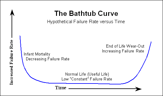
The simple explanation of the bathtub curve:

  • Product may have early life failures, perhaps due to manufacturing defects;
  • Then there is a long period of normal operation, with a constant and low failure rate caused by normal wear and tear and the random things that happen during the product life; and
  • At the end of the product life, the failure rates increase due to wear-out.

Manufacturer warranties are aimed to deal with the early life failures. Typically, early life failures show up in the first few hundred hours of operation for almost all electronic products.

Designing for Reliability

There is a huge amount of theory about how to design for electronics with a high reliability (a large mean time between failures), but a lot can be simplified down to some simple rules:

  • Try hard not to let electronics run hot – heat is the enemy of electronics;
  • Use quality parts from trusted manufacturers – cheaper is rarely better;
  • Run parts with plenty of margin from its rating – components that are not under stress last longer;
  • Test new designs – measure power use, self-heating and the effects of elevated temperature;
  • Understand the nature of your electronic components; and
  • Control the Bill of Materials – factory substitution not permitted!

Some practical considerations:

Electrolytic Capacitors

These are notoriously prone to failing as they age.

Failures are more likely the closer the part is run to its voltage rating, and at higher temperatures. Many electronic products that malfunction after 5-10 years can be restored just by replacing the electrolytic capacitors.

For better reliability, try to make sure electrolytic capacitors can be kept cool, select only parts with a known “hours” rating, and always have plenty of voltage margin. For example, if used in a circuit that will be run at 12 V dc, do not use a 12 V rated part – instead select parts rated for 16 V or 35V. This costs a few cents more but the time until failure is likely to double, or more.

Even better, change the design so electrolytic capacitors are not used at all.

Ceramic Capacitors

These are well known to suffer voltage effects: the capacitance value drops with dc voltage applied. The capacitance drop can be huge, so ceramic capacitors should be chosen with a voltage rating significantly above the normal operating voltage, a factor of 5x or more is preferable.

Resistors

Resistors of any kind should never run hot.

Sometimes, though, resistors need to dissipate power. If that is the case, make sure there is at least 2x margin – if a resistor needs to dissipate 200 mW, then use a 1/2 W rated part.

Semiconductors (transistors, MOSFETs, diodes, and similar)

Like everything else, make sure these are not run close to their ratings.

Many semiconductor parts need to carry high currents – for example, semiconductor switches, MOSFETs used in dimmers, and so on. When these parts are used, check the effects of heating and temperature rise and keep this within safe limits. MOSFETs and other parts have a “safe operating” graph provided by the manufacturer – make sure under all modes of operation the device is used  well inside that safe operating area. In addition, check general overall heating in the actual product, not just a bench prototype.

Wherever possible, have margin on ratings – for example if a transistor needs to carry 250 mA, use a part capable of handling 500 mA. This adds cost, but also makes products more robust and less prone to early failure.

Knobs, Dials and “Twiddly Bits”

Unless needed for customer control, such adjustments or adjustable components are prone to knocks, bumps and sometimes have temperature dependant effects.

Where possible such components should be avoided.

Solder Joints and Connectors

Back in the days when your author studied reliability, these two items were the poster-children of electronic failures. The two worst parts of electronics are solder joints and connectors!

Unfortunately, solder joints are the glue that holds all electronics together, and designing them out isn’t practical. The best we can expect is that the manufacturer uses a well-characterised process compliant to IPC standards, and that they use an inspection process.

Inspection processes also add cost!

Connectors are also well-known to cause electronic failures. Wherever possible, connectors should be eliminated. If connectors must be used, then consideration needs to be given to:

  • How much current passes through the connector pins?
  • Should there be spare or redundant pins?
  • And probably the most important: carefully consider gold plating in connectors.

Connectors where dissimilar metals meet (gold plug / tin socket) should NEVER be used, these will always lead to unreliable operation.

Even gold plating needs careful consideration – the cheapest flash gold can be so thin that it may not be useful. And of course, the more gold used, the more expensive the connector.

The Summary of Designing for Reliability: avoid well-known problem components, use known quality parts, have margin from ratings, use gold in connectors, have inspection of soldering processes.

Basically, a bunch of things that add cost.

Manufacturing Burn-In

Sometimes, products can be run in the factory where they are made. This might be for a few minutes, or hours, or longer. Often when done there is some degree of stress applied – for example, a relay or dimmer controlling a large load.

The objective of burn-in is to find those products with early life failures (refer back to the bathtub curve), and ensure those are dealt with before the product ends up in the hands of customers.

Burn-in also adds cost.

Reliability Prediction

Is it possible to predict reliability? For example to try and calculated the MTBF of a new product?

Like all disciplines, the reliability engineers will say that yes, this is possible.

A significant amount of effort was put into reliability analysis and prediction by defence and telecoms companies from the 1960’s up until about the 1990’s. This has lead to a range of prediction methods, of variable quality.

Much of the basis for these prediction methods is now very dated and many modern electronic components have better properties than the parts used when the prediction methods were worked out. 

Nevertheless, the prediction methods available are the only widely understood and accessible tools we have, so we need to use them but also understand their weaknesses. The predictions using these tools are probably conservative – that is, in reality we expect a larger actual MTBF. 

Probably the best known prediction methods are MIL-HDBK-217F, commonly used for military (and everything else) electronics and Bellcore/Telcordia, commonly used for telecoms.

Modelling, use, and application of these standards and their associated software is complex and usually the domain of professionals. For MIL-HDBK-217F, the simplified “parts count” method allows a fairly easy estimation that most design engineers can perform. This method takes no account of the Design for Reliability section above, so for example ensuring components are not stressed will have no bearing on the result. 

There are a range of software packages used for reliability analysis and prediction, for example, RelCalc. 

For design engineers that want an estimation of MTBF based on the parts count method, the Reliability Analytics Toolkit website has an online calculator.  

Measuring Reliability

Easy right? Get a failure – count them.

Actually, it’s not that easy.

Not all Failures can be Counted

Some failures must not be counted, because reliability is about physical things, and about the inherent behaviour of the manufactured product.

It’s not OK to count:

  • User or Installer error or damage;
  • Manufacturer using the wrong component; and
  • Software or firmware that does not function as desired.

These are unfortunate and may need rectification, but they are not failures that count toward calculating an MTBF.

There are also other kinds of product behaviour that may be undesirable but are also not counted – the above are the major things that must be ignored.

Why?

  • An installer fitting wiring incorrectly in a terminal or dropping a product the smashes it might reveal design improvements that could be made, but do not represent wear-out or degradation over time.
  • A manufacturer using the wrong part is a process failure, and should be corrected by the manufacturer.
  • Software or firmware does not degrade over time. It might not do what was specified, or what is expected. This includes strange and intermittent behaviour (timing related so called “Heisenbugs”).

There are also other complications when doing reliability testing, related to when the measurement may start again – these are for the reliability professionals and to keep things simple we can ignore them.

Why Measure Reliability?

Two major reasons for measuring reliability and estimating a product MTBF:

  1. Measured data is better than prediction – so any MTBF number based on actual hours of a product in use is preferable to prediction.
  2. Common factors or trends might be seen, allowing a design improvement.

Practical Aspects of Reliability Measurement

Measuring reliability needs two important organisation considerations:

  1. Failed products need to be returned, analysed, and the underlying fault recorded.
  2. This is a long-term commitment.

To expand on these:

When making products that have a long market and installed life (5-10 years), then the only way to measure actual failures is to get failed items returned. If they are not returned, then no meaningful information can be gathered.

For low value products, it might be acceptable for example for a wholesaler to send in a monthly or quarterly note of number of failed items thrown out and replaced. There is no analysis, no information on underling fault, and so while a very small amount of information might be available to determine a rough MTBF number, there is no detailed information available.

Only by analysing each failure is it possible to determine common underlying causes that may be used to improve a design.

To seriously analyse product failures therefore needs the supplier to receive back failed product, analyse the failures, try and pick common faults, and do something about them. These are all expenses that need a long term view of continuous product improvement.

Expectations

What is a reasonable mean time between failures?

What is the mean time between failures of some actual products?

This is covered in Part 2.

Scroll to Top

Register for news and notification of updates

Why Register?  Registering makes it easier to inform our customers and users about new updates and features.

We won’t fill your inbox with spam emails and we will never sell any mailing lists.